| HOME |
|
Infos |
|
|
|
DMX |
|
|
|
Miscellaneous |
|
|

DMX dimmer pack
This single-phase dimmer pack is a quite simple design. Nevertheless, it is suitable for most tasks thanks to its power linearisation, the full resolution of 256 steps and the possibility of operating individual channels in switch mode. With up to eight channels of 2 kWmax. each and overtemperature protection, even larger systems can be implemented without any problems. The modular design makes the dimmer easy to repair.
A DMX dimmer pack consists of the following modules:
1 DMX Transceiver
1 ZC-Detection
1-8 Dimmer modules
The dimmer pack can run either on a conventional DMX firmware or an RDM firmware.

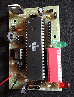
DMX Transceiver (Rev. 3.2)
With this module, DMX data can be sent and received. However, due to using a microcontroller, this circuit is not ideal for beginners.
The Transceiver is suitable for bidirectional communication (e.g. RDM according to ANSI E1.20) due to the complete connection of the RS485 converter.
Industrial-quality circuit boards are available in the shop.
 part list
| IC1 IC2 IC3 D1 LED1 LED2 R1 R2,3,4 C1,2 C3,4 C5,6 SW1 Q1 connectors |
ATmega8515-16PU (+socket!) 75176B (+socket!) 7805 1N4007 LED 5mm red LED 5mm green 10k (PT10-S) 390 Ohm 27pF 100nF 100µF DIP switch (10x) 8MHz (HC49) pin header RM2.54 |
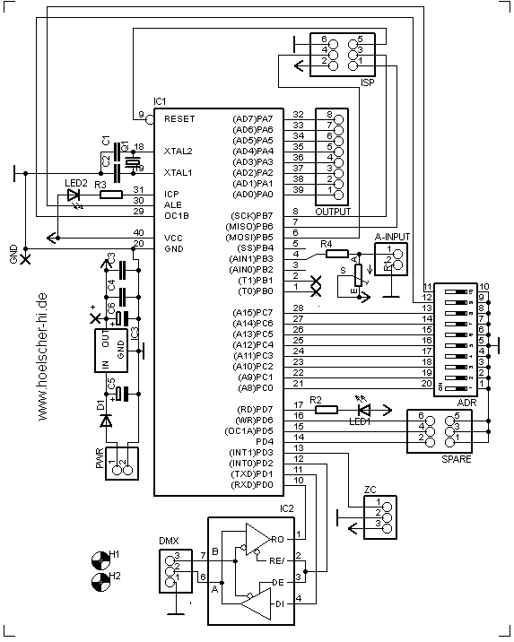
As you can see, the circuit is quite simple: All the magic happens in firmware within the MCU (IC1). It is transferred to IC1 via the "ISP"port. The start address and special options (if any) are set via ADR. The LEDs serve as status indicators. The voltage regulator IC3 ensures a stable operating voltage of 5V. Q1 and C1,2 are needed for an operating frequency of 8MHz. The RS485 converter IC2 allows the MCU to communicate with the DMX universe. With the help of "Spare", various firmware options can be jumpered. Via A-Input, an analogue threshold value (e.g. for thermal protection) can be read.
A supply voltage between 9V and 12V dc is connected to PWR. The DMX Transceiver itself requires <300mA. When selecting the power supply, all loads must be taken into account.
pcb layout (48 * 76 mm^2; 300dpi) |
placement |
The transceiver is connected to the DMX bus as shown in the next diagram:
Attention: Pin 3 of the XLR connectors is connected to the middle pin of the PCB connector!

Instructions for programming and selection of clock sources can be found under 'Resources'.
After the crystal is selected as the AVR's clock source, one of the two dimmer pack firmwares should be transferred to the DMX transceiver. The actual development work lay in these firmwares: The relevant channels are filtered from the DMX data stream and the appropriate firing times are calculated. With each zero crossing a timer synchronises itself to fire the desired triac at the right time. (This principle is known as forward phase control or leading edge dimming).
ZC Detection
This zero-crossing detection is needed to synchronise the microcontroller with the mains. It is connected to "ZC" on the Transceiver.
schematic |
part list |
|
 |
OK LED R1A R1B R3 |
4N33 LED 3mm 27k / 1W 27k /1W 10k |
The positive half-wave enables the LED of OK via R1 (the negative half-wave is diverted via the LED). Due to thermal issues, R1 consists of two serial resistors that share the power loss. If OK is conductive, ZC is pulled to GND. During the negative half-wave, ZC is pulled to 5V by R3. A clean square wave with a duty cycle of approx. 50% should be present at the output, whose edges correspond to the zero crossings.
Placement

dimmer modules

To control spotlights, transformers or motors with the TTL levels of the DMX Transceiver or an Arduino, you need the following dimmer modules or solid state relays without integretad zero-crossing switching.
The dimmer modules were tested with 500W inductive load and with 2000W ohmic load. They operate in a temperature range from -20°C to 80°C.
schematic |
part list |
|
 |
OK1
T1 LED1 R1 R2 R3 R4 C1 C2 OUT |
MOC3022
TIC 2XX LED 3mm 390Ω 360Ω 470Ω 39Ω / 0,5W 47nF / 630Vdc (MKS4 / RM7,5) 10nF / 630Vdc (MKS4 / RM7,5) 6,35mm flat pin connector |
As soon as voltage is applied to the LED of the optotriac OK1, it fires and controls the gate of the power triac T1 via R2. C2 and R4 form the snubber network of the triac. The filter consisting of R3 and C1 is required for operation with inductive loads.
I designed a common board for the power modules of my dimmer and switch packs. One board carries four channels and one zero-crossing detection. Also there is a single sided layout for running reduced loads. If less channels are needed, the board can be cut to the required length. Different optotriacs are used in the power modules of dimmer and switch packs!
Layout (112mm x 40mm; 300dpi)
Placement

A toroidal choke with an iron powder core is looped into each output. The inductance dampens the transients of the phase control and thus prevents hum in the sound system and buzzing of filaments. To estimate the damping factor, a 'rise time' is often specified in commercial dimmer packs. This is the time (in µs) in which the current rises from 10% to 90% after the triac fires. After transforming a differential equation, the required inductance can be calculated as follows:
L = (t*U)/(2.198*I)
with 't' as the rise time in [s], 'U' the voltage in [V] and 'I' as the current in [A]. A rise time of 80µs (approx. 1mH@10A) is common. In highly sensitive studio environments, rise times of up to 500µs are used.
Thermal protection
In the course of increasing the power handling capabilities of the dimmer modules, a thermal protection was necessary to prevent damage by shutting down the outputs. For this purpose, an NTC and the trimmer potentiometer R1 form a voltage divider, which triggers the shutdown if its value falls below 1.25V. I chose the following values for the voltage divider:
| R1 NTC |
10k (PT10-S) 6,8k @20°C |
For calibration, the NTC should first be heated to the desired threshold temperature (45°C - 75°C). Then R1 is first set to the right end stop (fully turned right) and then slowly turned back until the red LED lights up and the dimmer switches off.
DMX Firmware
Switch mode
To drive individual channels in switch mode, proceed as follows:
1.) Switch off dimmer pack.
2.) Set DIP10 and the DIPs of the channels to be switched (1-8) to the ON position.
3.) Switch on the dimmer pack.
4.) Set start address, DIP10 = OFF. (The channel masking is stored in the EEPROM).
60Hz operation
By setting the Spare1 jumper, the dimmer can also be used in 60Hz grids (i.e. USA).
Debugging
In order to achieve an easy error detection, I have implemented an error indicator:
During start-up, the ErrorLED should light up. A change in the relevant DMX channels is indicated by the green LED flashing.
The following codes are repeated continuously until the issue is resolved.
| Pattern | Error | Solution | |
|
|
flashing | There is no signal present at the Transceiver. | Connect the Transceiver to the DMX bus. |
|
|
double flashing | The signal is not recognised as DMX. Not all required channels are received. |
Swap D+ and D- on the DMX connector. Transmit more channels or select a lower start address. |
|
|
fast flashing | The ZC detection is not connected. | Connect the ZC detection. |
|
|
on | Overtemperature | Allow to cool. If necessary, provide better heat sinks. Assemble thermal protection and use A-In. |
RDM Firmware
RDM operation is activated via DIP10: In the ON position, DIP1 to DIP8 are used as part of the RDM device address. In the OFF position, DIP1 to DIP9 are used as the binary DMX start address as usual.
60Hz operation
By setting the Spare1 jumper, the dimmer can also be used in 60Hz grids (i.e. USA).
RDM parameters
The following settings can be accessed via RDM:
| Parameter | ID | Bytes | Function |
| DMX Start Address | 00F0 | 2 | DMX start address |
| Personality | 00E0 | 2 | dimmer or switch mode |
| Min Limit | 0300 | 8 | Preheat |
| Max Limit | 0301 | 8 | Topset |
| Error Scene | 0302 | 8 | error scene on signal loss |
| Status Messages | 0030 | 9 | returns device status |
| Device Label | 0082 | 0..19 | name of device |
| Manufact. Label | 0081 | 5 | name of manufacturer (Henne) |
When setting the error scene, a "signal hold" functionality can be chosen by setting all eight channels to 255.
Debugging
In order to achieve an easy error detection, I have implemented an error indicator:
During start-up, the ErrorLED should light up. A change in the relevant DMX channels is indicated by the green LED flashing.
The following codes are repeated continuously until the issue is resolved.
| Pattern | Error | Solution | |
|
|
flashing | There is no signal present at the Transceiver. | Connect the Transceiver to the DMX bus. |
|
|
fast flashing | The ZC detection is not connected. | Connect the ZC detection. |
|
|
on | Overtemperature | Allow to cool. If necessary, provide better heat sinks. Assemble thermal protection and use A-In. |


